I undertook many projects this year, some that I did not even think would be something I would be doing and others that had been on a slow back-burner for years. I will describe one that was on a slow back-burner, doing IoT with the ESP8266 devices.
A bunch of my friends decided to get into hydroponics which I think is a good activity to start for it gives lots of avenues for learning and growth (no pun intended).
So, we each bought a hydroponics system for about S$160 and is shown in the photo all set up in the balcony at home. It takes up probably about a 2m by 1m space.

But before I set that up, I decided to learn all that I can and signed up for a hydroponics class that was held at the Kok Fah Technology Farm along Sungei Tengah Road. A whole day course to understand the terminology and ideas behind the hydroponics movement. It was a good course.
With that out of the way, and learning a lot about “total dissolved solids”, “electrical conductivity” etc, I decided that for the setup I will roll out, I will want to have the system be monitored remotely so that if this is a viable model, perhaps help others to replicate as well.
Hence, I started to read up and learn all that I could about using both the Raspberry Pi as well as the Arduino for the project to monitor two aspects: temperature of the water that will be flowing in the tubes and the total dissolved substances value that will indicate the nutrient level of the water that is flowing to the plants.
Over the years, I’ve acquired a bunch of Raspberry Pis, Arduino boards and even the ESP8266 devices with the expectation that one day I will use them for something that is interesting and not just for fun. And, I am glad that those devices came in handy for my little hydroponics automation project.
I bought the following sensors: a) a temperature sensor DS18B20 from AliExpress.com which is a digital sensor and the sensor in the probe is from Maxim Integrated. The sensor does parasite power and so can work without being supplied with external power. b) a tds/ec sensor also from AliExpress.com which is an analog device (more about this choice later).
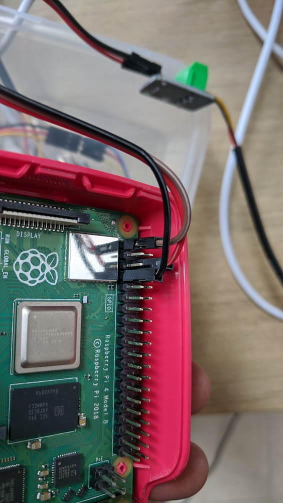
My first attempt was to get the Raspberry Pi to be the platform on which these two sensors will be connected to. Very quickly, it was apparent that the RPi only has digital input pins and if I need to plug in an analog sensor, I will have to do some additional circuitry to make that happen. In general, that is fine, since this is my first attempt at doing something that is essentially an IoT project.
I got the RPi4 plugged in with the temperature sensor, ran the code – a python code from the manufacturer of the sensor and viola, it worked and worked really well.
Here’s a video of the RPi working via a vnc setup (right side of the video) and on the left side the Arduino code for a second setup with an Arduino Yun device.
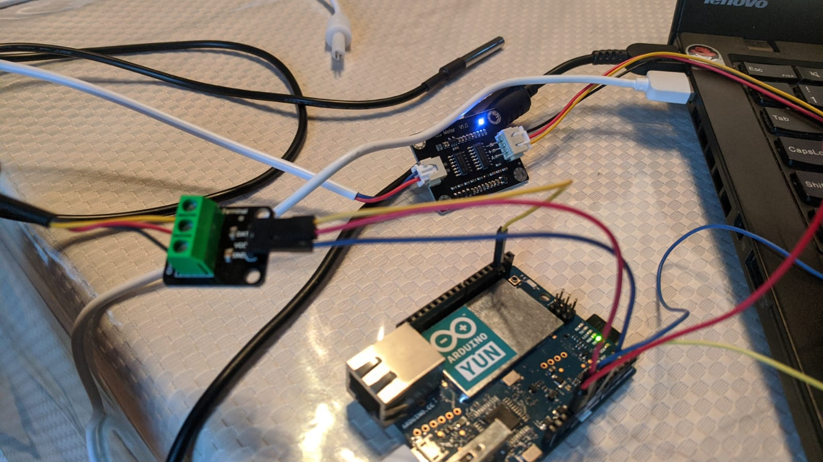
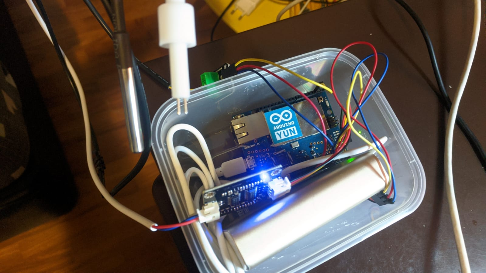
Because the RPi does not have analog input pins, and since i did not want to create additional circuity to do ADC (analog to digital conversion), I created a second setup with the Arduino Yun which does have both digital and analog input options.
The Arduino Yun is an interesting part of the Arduino family (although, it has sadly been deprecated) as it has both the microcontroller portion as well as a bridge to a Linux operating system (albeit running OpenWRT meant for the Yun) which allows for the Yun to be accessed via a wifi/wired link. Unlike products that are proprietary, even though the Yun I have has been deprecated, the device is open sourced and the code etc are all available to be used and worked on. The power of open source, open collaboration wins here handily.
Given the success of working with the Yun, I figured that the work is done. But no! I wanted to further optimise the setup as the Yun should really be a prototyping board rather than a deployed in production board mainly because, in my case, I only need two sensors that need to be accessed and the Yun has lots of other pins for a larger project.

And I did have in my possession a bunch of ESP8266-01 boards (ESP-01 in short), whch has a built in wifi capability, and can be programmed just as one would the Arduino. And these boards have two input pins that I could use and so, my attention shifted to making the ESP-01 do what the Yun was doing.
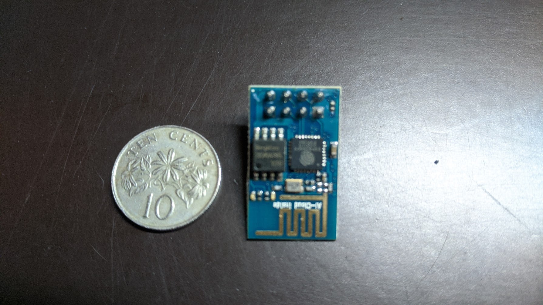
The ESP-01 is designed with some use case considerations: a) it can only handle 3.3v as the input b) the board can be flashed via shorting to ground of one pin and has to be done manually. These constraints or considerations, I am sure, is the reason why these boards are about S$1.50 or so. So to program the ESP-01, you will need a 3.3v supply and a way to get to the USB port of you laptop and that is all done via a USB UART similar to this.
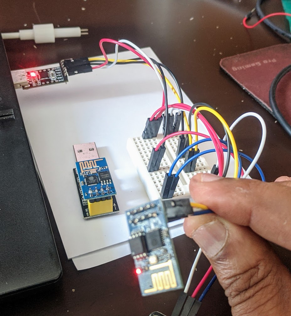
The BIG challenge with the ESP-01 is that the code needed to make it work is not readily available or if available, does not explain well enough. I watched lots of videos and learned bits here and there about the device. The makers of the ESP8266 devices, Espressif Systems, have published a lot of their code to work these devices and sadly, the ESP-01 for some reason is not as well documented as it should have been. There seems to be lots of folklore-like statements in the videos and blogs that describe the device and how to work it. No one seemed to be making references to the actual datasheet for the device from Espressif – which is the primary and authoritative source. There are many sites that discuss the later ESP8266 devices – mainly because they have more GPIOs – but it is kinda disappointing to have the ESP-01 information scatttered all over.
So, for sanity said, here’s what I had to ave figured out and made work. I’ve placed the ESP8266 01 data sheet here . It is from the manufacturer (I guess subcon) AI-Thinker.com.
Here’s my schematic for my setup is shown here (yes, I could have done it with Fritzing.org – which I did).
[will add the layout – tbd]
I will be placing all of the code on gitlab.com.
To be continued …
2nd December 2020 Update: Turns out Adafruit has 4 channel ADC breakout board that I could use with the ESP-01. Thanks to Steve Mercer for the hint. And a related tutorial as well – https://microcontrollerslab.com/ads1115-external-adc-with-esp32/.
